

Almost every factory distribution room has one: a row of cubicles with contactors, fuses and a controller showing the power factor. It is the least discussed equipment in the building and, per yuan spent, one of the most effective.
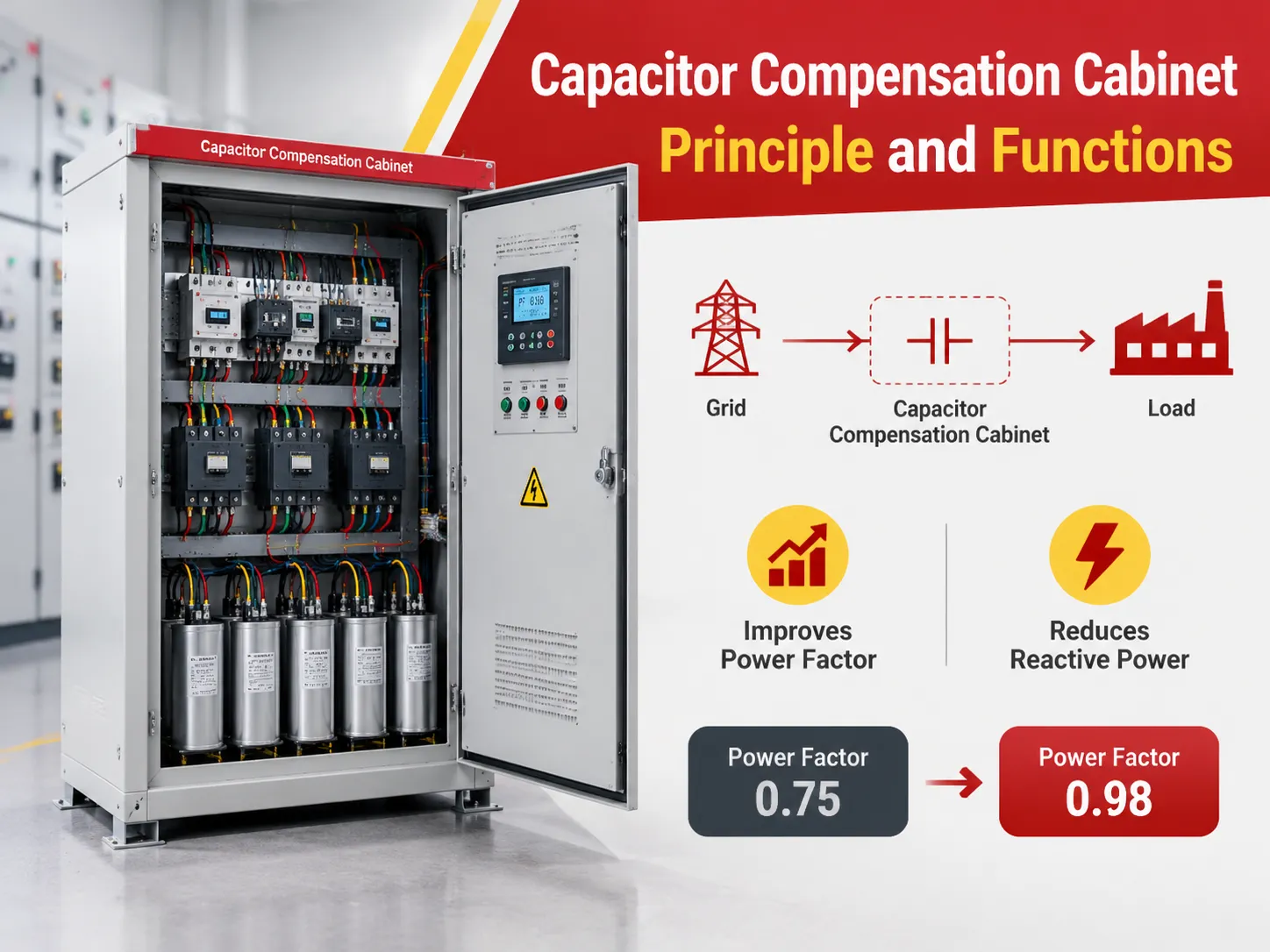
A capacitor compensation cabinet, also called a reactive power compensation cabinet, is a packaged set of switched capacitors that raises the power factor by supplying reactive power close to where it is consumed.
Why a Plant Needs One
The loads that do the work in a factory are mostly inductive. Motors, transformers, welding equipment, induction heaters. To run, they need a magnetic field, and building that field takes reactive power, which the load absorbs and returns sixty times a second.
Reactive power does no useful work. It does, however, occupy capacity: it flows through the transformer, through the cables, through the switchgear, and every amp of it contributes to I²R losses while leaving less headroom for productive load.
Three consequences follow, in increasing order of how much they cost you:
- Power factor drops, and the utility applies a reactive adjustment charge.
- Line and transformer losses rise, so you pay for energy you never use.
- Effective capacity of the distribution equipment shrinks, which usually shows up as an argument about needing a bigger transformer than the load justifies.
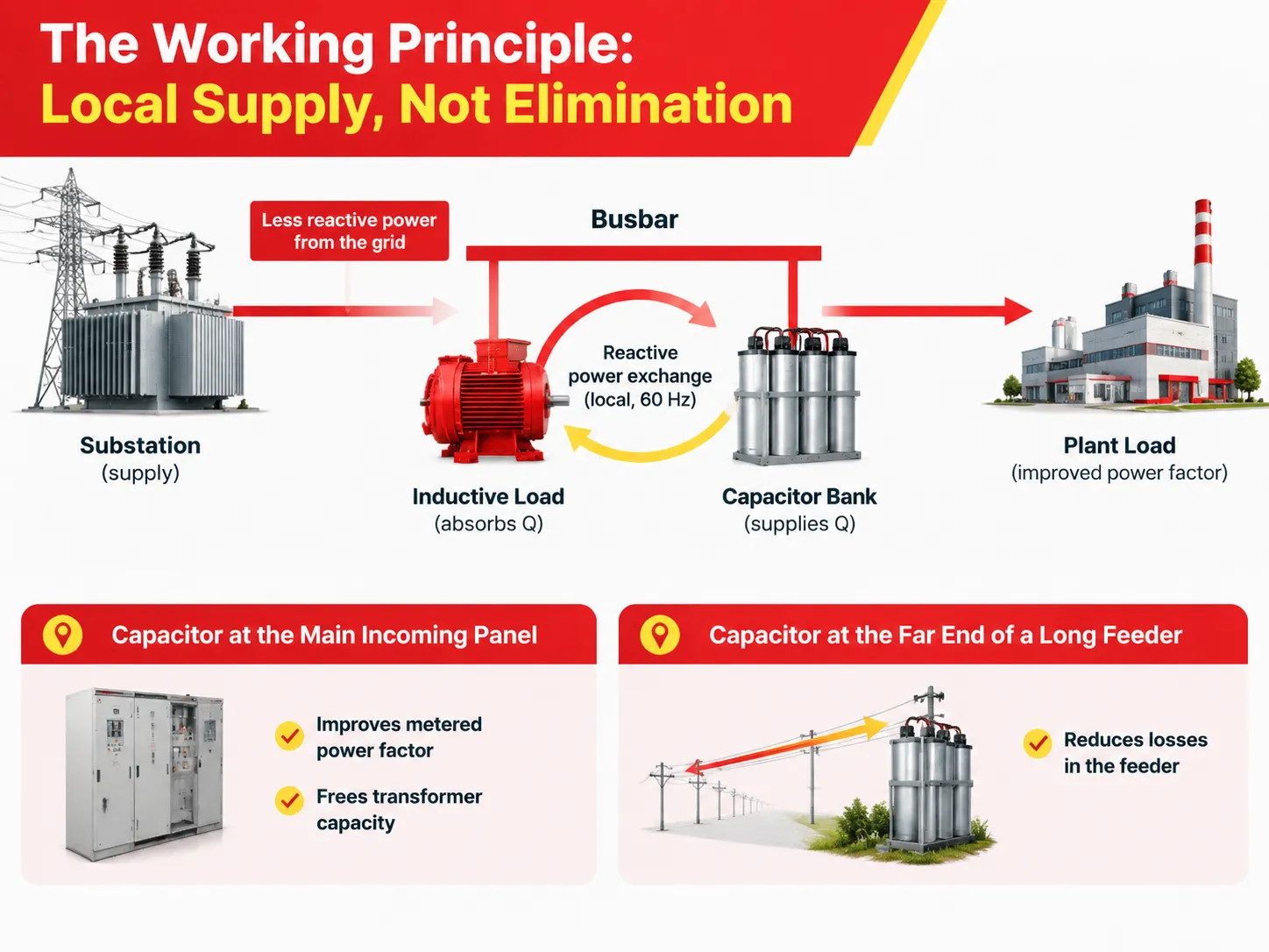
The Working Principle: Local Supply, Not Elimination
The one thing worth understanding clearly is that compensation does not remove reactive power from the system. It changes where the reactive power comes from.
An inductive load absorbs reactive power while its field builds and releases it while the field collapses. A capacitor does the opposite, releasing while the inductor absorbs and absorbing while the inductor releases. Put them on the same busbar and the exchange happens between the two, locally, sixty times a second.
The net effect at the incoming supply is that far less reactive power has to travel from the substation to the plant. The power factor at the metering point rises, and the losses associated with that travel disappear.
This is also why the location matters. A capacitor bank at the main incoming panel improves the metered power factor and frees transformer capacity. A bank at the far end of a long feeder also reduces the losses in that feeder. Same capacitors, different benefit.
What It Actually Delivers
Power factor above the tariff threshold. The most immediate and most measurable result. Once the site clears 0.9, the reactive adjustment charge stops.
Lower losses. Current in cables and transformer windings falls in proportion to the power factor improvement, and losses fall with the square of current. On a heavily loaded transformer this is a real number, not a rounding error.
Released capacity. A 1000 kVA transformer at 0.75 power factor delivers 750 kW. At 0.95 it delivers 950 kW. Two hundred kilowatts of capacity you already own and are not using.
Better voltage. Compensation reduces the voltage drop along the feeder, which is often what actually fixes the flickering lights at the end of a long run.
Where It Stops Working
Two conditions, and both are common enough to check before ordering anything.
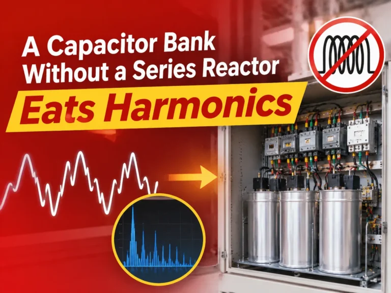
Harmonics. Capacitive reactance falls as frequency rises, so harmonic current concentrates in the capacitors. A bank without series reactors on a distorted supply will overheat, swell and fail repeatedly. Detuned reactors at 7% or 14% are not accessories; on any site with VFDs they are part of the specification. The filter reactor range exists for exactly this pairing.
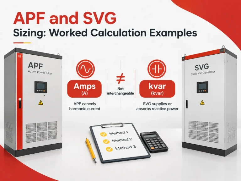
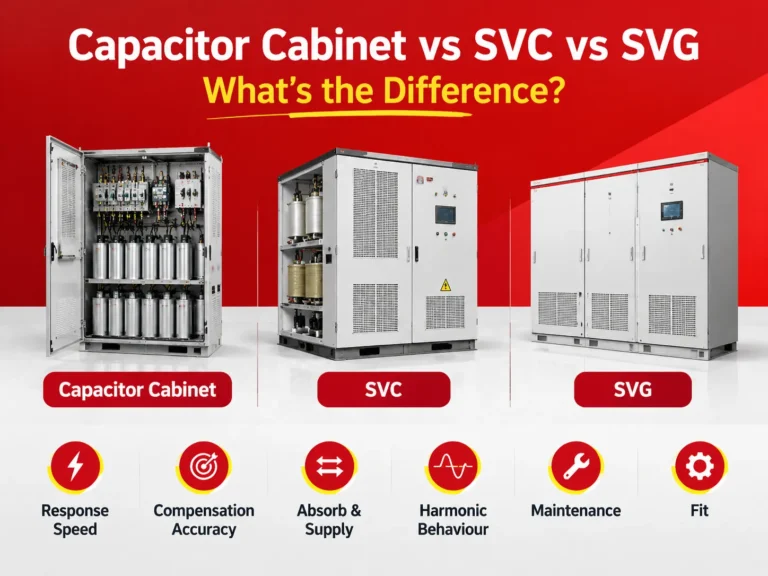
Fast-changing loads. A stepped bank corrects the average, and it does so after the fact. On welding lines, press shops and crane duty, the contactors end up switching constantly, overshooting and undershooting, and wearing out. That is the case for active compensation, where the output follows the load instead of stepping behind it.
Between those two extremes sits most of the real world: a stable base load that a capacitor bank handles well, plus a fluctuating component that needs something faster. The economic answer is usually both, with the capacitors carrying the base.
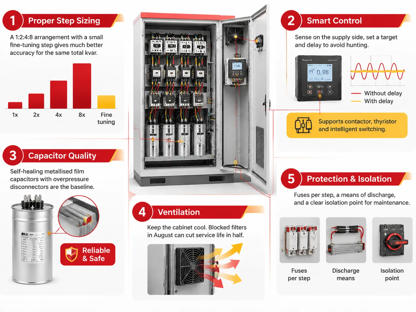
Specifying One Properly
Step sizes matched to the load profile. A bank of equal steps gives coarse resolution. A 1:2:4:8 arrangement with a small fine-tuning step gives much better accuracy for the same total kvar.
A controller that measures what matters. The power factor controller should sense on the supply side of the bank and be set with a target and a delay that avoid hunting. Controllers that chase every fluctuation shorten contactor life dramatically. The power factor controller range covers contactor, thyristor and intelligent capacitor switching, which matters because the switching technology dictates the control strategy.
Capacitor quality. Self-healing metallised film capacitors with overpressure disconnectors are the baseline. Cheap capacitors in a hot cabinet fail early, and the failure mode is not graceful.
Ventilation. Capacitors and reactors both produce heat, and cabinet temperature is the single biggest driver of service life. A cabinet with blocked filters in August is a cabinet running at half its design life.
Protection and isolation. Fuses per step, a means of discharge, and a clear isolation point for maintenance. Basic, and frequently skipped in low-cost cabinets.
FAQ
How much compensation do I need?
Work from the bill. Calculate the current power factor from active and reactive energy, decide the target, then apply Qc = P × (tanφ1 − tanφ2). For most plants, 0.5 kvar per kW of average load lifts the factor from around 0.78 to 0.95.
Can a capacitor cabinet cause overvoltage?
Yes, if it over-compensates or stays connected during light load. That is a control and step-sizing problem, and it is why the controller’s target and delay settings matter as much as the capacitor rating.
Do capacitors still make sense where an SVG is installed?
Usually yes. Capacitors cost a fraction of what active compensation costs per kvar and handle the steady base load perfectly well. The SVG is there for the part that moves.
How long do the capacitors last?
Ten to fifteen years in a well-ventilated cabinet with a clean supply, far less in a hot cabinet on a harmonic-rich busbar without reactors. Capacitance should be checked periodically, since ageing is gradual and nobody notices a bank that has quietly lost 20% of its rating.