
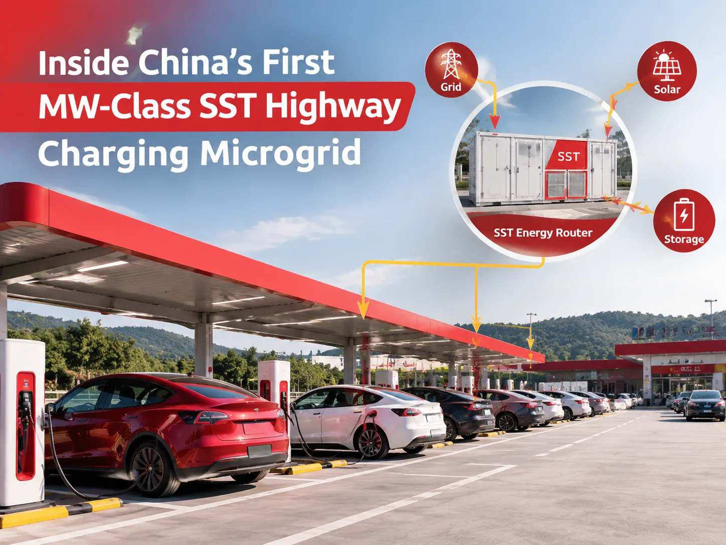
Anyone who has driven an electric car on a holiday weekend knows the pattern. You arrive at a service area, every stall is taken, one side of the car park is full while the other sits half empty, and the queue moves at the speed of the slowest charger.
The problem is not usually a shortage of electricity in the region. It is that the two halves of a service area are fed by different feeders, sized for their own average load, and neither can borrow from the other when demand turns tidal.
A demonstration project in Guangdong set out to fix exactly that, and it is worth looking at because it shows what medium-voltage solid-state transformer hardware can do when it is used as an energy router rather than as a transformer.
The Project in Numbers
The site is the Dahuai service area on the Shenhai Expressway in Jiangmen, Guangdong. It was commissioned on 28 September 2025 and has since run for roughly 180 days without a supply interruption.
- Two solid-state transformers, one per zone: 1.25 MW for the east zone, 1 MW for the west.
- An 800 m DC cable linking the two zones on a common DC bus.
- Two 10 kV feeders, one per zone, now bridged by that DC link.
- Seven 600 A liquid-cooled charging cables on site.
- 113 charging bays in total: 51 east, 33 west, plus existing operational stalls.
Everything else in the project follows from that 800 m cable. Once the two zones share a DC bus, “east” and “west” stop being separate electrical islands.
Why the DC Link Is the Interesting Part
The obvious way to share power between two zones is to run an AC cable and parallel the transformers. That works, but it drags along the usual problems: two sources that must stay synchronised, circulating currents, and protection that has to coordinate across both.
Linking them on the DC side avoids most of that. Each SST converts its own 10 kV feeder down to a common DC level, the two DC buses are tied together by a cable, and power flows in whichever direction the control system decides. No synchronisation, no phase angle to match, and the transfer happens in the power electronics rather than in a mechanical switch.
The result is a genuine energy bridge between two feeders that were never designed to cooperate.
What Actually Changes at the Charging Bay
Cross-zone dispatching
When one zone fills up and the other is quiet, the system moves power to the busy side automatically instead of telling drivers to drive around the car park. Peak holiday traffic is exactly the tidal pattern this is built for. The operator reports several tens of thousands of charging sessions served since commissioning.
Liquid-cooled cables
Seven 600 A liquid-cooled cables carry the current that conventional air-cooled cables cannot, which is what allows the headline charging rate. The marketing figure is one kilometre of range per second at peak; what matters practically is that the average power across the newly built outlets exceeds 72 kW, which is a real improvement over the 60 kW units that were standard a few years ago.
Enough bays to stop the queue forming
113 positions does more for the driver experience than any single charger rating. A queue at a service area is a capacity problem, not a speed problem, and the project addresses both at once.
Three Operating Modes, One Controller
The two SSTs act as the brain of the site. They switch between operating modes depending on what the microgrid needs:
- Grid-tied, normal operation: each zone draws from its own feeder, with the DC link balancing the difference.
- Cross-zone transfer: one zone at full load, the other light, and power is routed across the DC bus to where the vehicles are.
- Constrained or islanded conditions: the SST holds the busbar voltage, regulates reactive power and limits output to keep the microgrid inside its operating envelope.
Voltage regulation and reactive power control come free with the topology, because the SST is already an inverter. That is a capability a conventional 10/0.4 kV transformer simply does not have; it transforms and the rest is up to whatever compensation equipment you bolt on beside it.
What This Proves, and What It Doesn’t
It proves the architecture works in a real, unmanned, high-traffic environment: PV, storage and chargers can all connect to the same DC bus, zones can share power, and the site keeps running through holiday peaks without a dedicated engineer on shift.
It does not prove that every service area should be rebuilt this way. A site with two well-sized feeders and predictable demand may not need the DC link at all, and an SST costs more than a transformer plus a switchboard. The case strengthens where three conditions coincide: constrained feeder capacity, strong tidal demand, and a need to integrate PV or storage on the same bus.
For highway networks, those conditions are common enough that the demonstration has value beyond the single site. The same building blocks, at smaller scale, are what the power electronics behind a charging hub already use for voltage support when the grid is weak and the load steps are large.
FAQ
What is a solid-state transformer?
A transformer that works by switching rather than by magnetic induction at line frequency. It converts AC to high-frequency AC or DC, isolates through a small high-frequency transformer, and reconstructs the output at whatever voltage and form the load needs. It is smaller, actively regulated, and can output DC directly.
Why use DC rather than AC to link the two zones?
Because DC removes the need to synchronise two sources. Power flow is set by the converters, so there is no circulating current and no phase-angle matching problem, and the response is limited only by the control loop.
Can existing service areas be retrofitted?
Partially. Adding an SST and a DC link to an existing AC site is possible, but the protection scheme, the earthing arrangement and the layout all need rework. Greenfield or major-upgrade projects are where the economics work best.
Does the site still need power factor correction?
The SST provides voltage and reactive control at the DC interface, but the chargers themselves and the site’s other AC loads still have their own power quality characteristics. Reactive compensation and harmonic filtering remain part of the design, whether handled by the converter or by dedicated equipment.